Table of Contents
- Why Cable Sizing Can Make or Break Your Solar & BESS Project
- Step 1: Define the Application Scenario & Select the Right Cable Type
- Step 2: Fast Cable Sizing Formula & Safety Verification
- Step 3: Quick-Reference Engineering Sizing Matrix
- Built for Reliability: Certified Quality Assurance & Customs Compliance
Why Cable Sizing Can Make or Break Your Solar & BESS Project
In utility-scale and commercial solar engineering, cable selection is frequently overlooked—until system failures occur. Undersized cables lead to severe overheating, high resistive losses, and premature insulation aging, while incorrect sheath materials cause rapid weathering and failure in harsh outdoor environments.
For international EPC contractors, developers, and wholesale distributors, getting cable specifications right is non-negotiable. Whether you are designing a rooftop commercial photovoltaic system or a containerized Battery Energy Storage System (BESS), this engineering guide outlines a foolproof, 3-step method to calculate wire gauges, verify voltage drops, and ensure maximum system efficiency.
Step 1: Define the Application Scenario & Select the Right Cable Type
Different segments of a solar and energy storage ecosystem require distinct cable specifications. Choosing the correct jacket material and voltage rating is the first line of defense against system downtime.
1. Photovoltaic DC Side (Solar Panels → Combiner Box → Inverter)
- Recommended Models: PV1-F or H1Z2Z2-K (certified photovoltaic dedicated cables).
- Key Features: Dual-insulation construction, exceptional UV resistance, and a wide operating temperature range of -40°C to +120°C, engineered for harsh outdoor exposures.
- Voltage & Specs: Systems operating at 1000V or 1500V require 1.8kV DC-rated cables (adhering to the standard that rated voltage must be ≥ 1.5 times the system voltage). Mainstream string wiring relies heavily on 4mm², 6mm², and 10mm² cross-sections.
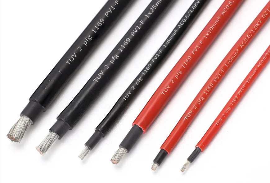
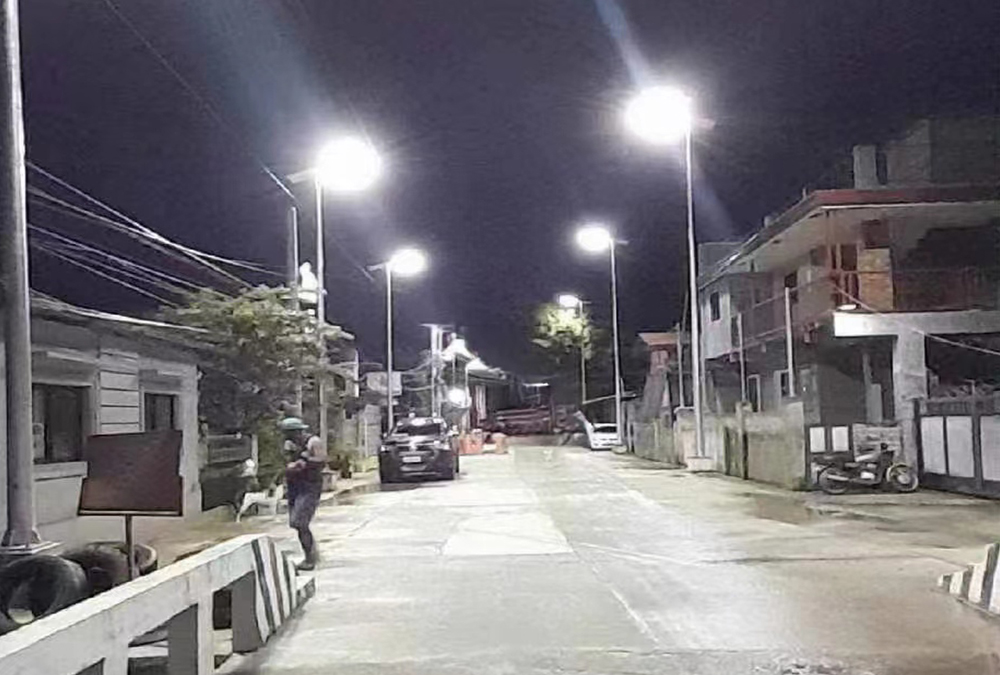
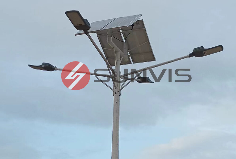
*Pro Tip: When wiring outdoor solar lighting systems, always ensure the DC cables match the specific IP65/IP67 waterproof ratings of the fixtures.
2. Energy Storage DC Side (Battery Cluster → BMS / PCS)
- Recommended Models: High-flexibility copper cables (RVV / RVVP) or specialized heavy-duty BESS DC cables.
- Key Features: Must withstand continuous high temperatures (≥ 105°C) to cope with continuous thermal cycles during heavy charge and discharge operations.
- Voltage & Specs: Compatible with 48V, 96V, or 1500V architectures. High-current battery clusters utilize robust cross-sections including 16mm², 25mm², 35mm², 50mm², and 70mm².
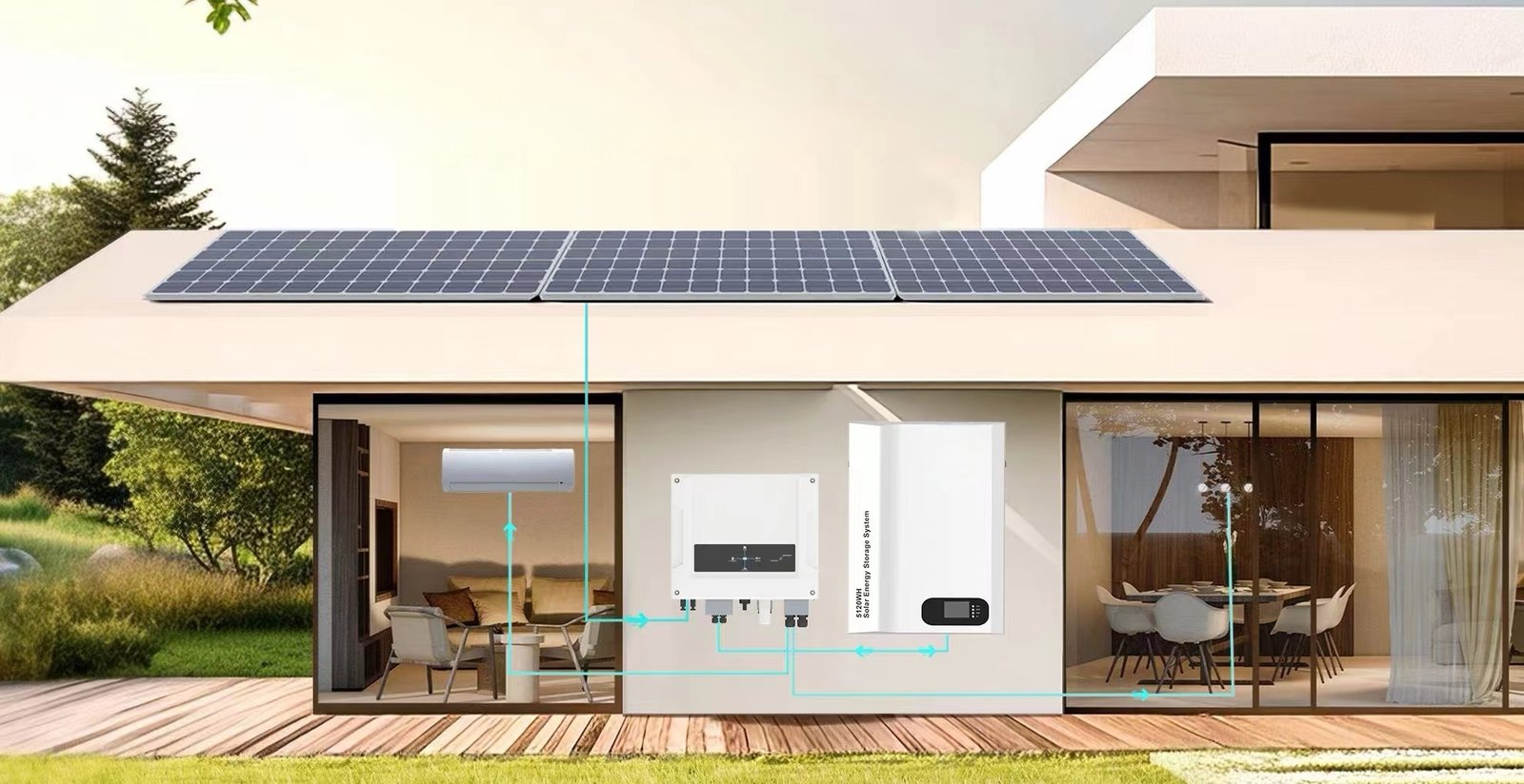
*Looking for complete storage solutions? Explore our commercial and residential energy storage systems.
3. AC Grid-Tie Side (Inverter → Grid Connection Point / Load)
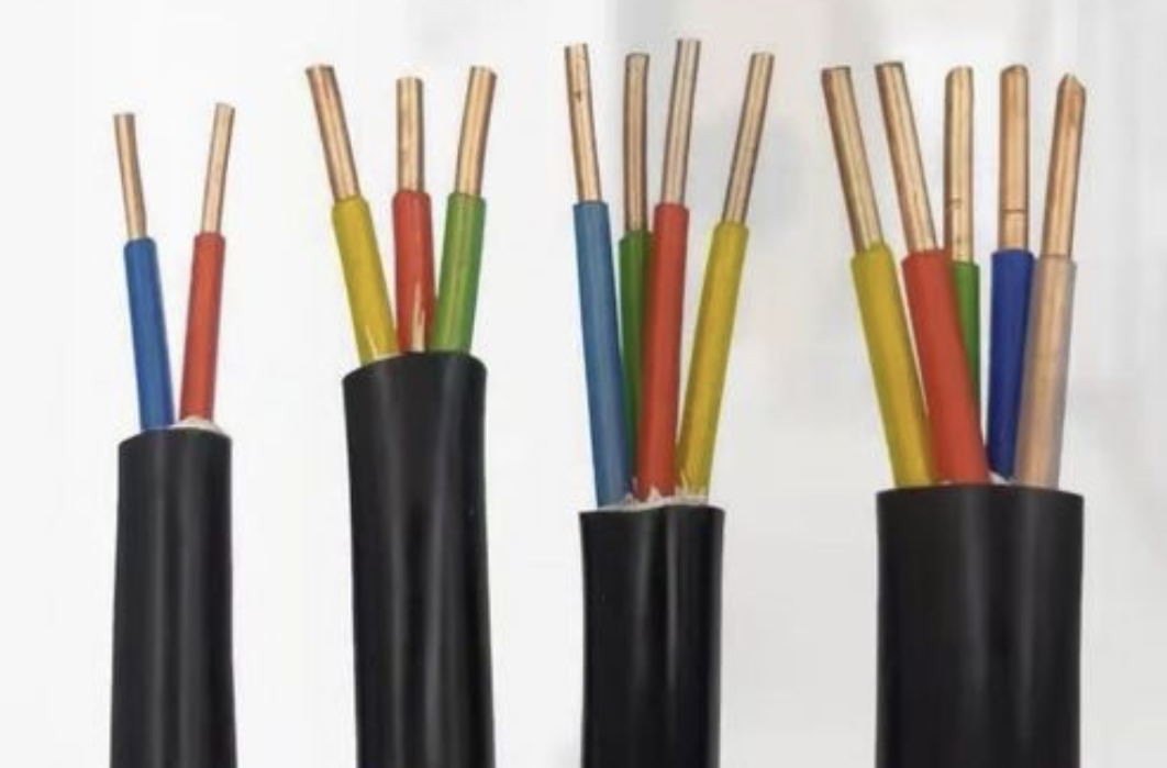
- Recommended Models: Copper-core XLPE insulated power cables (YJV/U1000 R2V). For direct burial or rugged outdoor trench routing, armoured YJV22/U1000 AR2V cables are mandatory to prevent mechanical damage from rodents or soil pressure.
- Voltage & Specs: Standard low-voltage grid connections utilize 0.6/1kV ratings. Standard 3-core configurations range from 3×10mm² to 3×70mm², with a recommended 20% safety capacity margin built into commercial tenders.
Step 2: Fast Cable Sizing Formula & Safety Verification
You do not need complex engineering software for initial estimations. You can determine the precise conductor cross-section in two quick steps:
Phase 1: Initial Sizing by Current Capacity
Use the rapid estimation formula for copper cables:
Cross-Section (mm²) ≈ Max Current (A) × 0.7
(Note: This formula applies to standard ambient temperatures ≤ 40°C with free-air routing.)
- Mandatory Safety Factors:
- PV DC Side: ≥ 1.56 × Short-Circuit Current (Isc)
- BESS DC Side: ≥ 1.25 × Max Charge/Discharge Current
- AC Grid Side: ≥ 1.25 × Inverter Rated Output Current
- Environmental De-rating Rules: If ambient temperature ≥ 40°C, scale up the wire gauge by 1–2 sizes. For bundled or conduit-routed cables, apply a 0.8–0.9 multiplier. For direct underground burial, apply 0.8–0.85.
Phase 2: Voltage Drop Compliance Check
To comply with international standards (such as IEC / GB 50797), voltage drop verification is mandatory to prevent efficiency loss:
- DC Side Allowable Drop: ≤ 2% of system voltage.
- AC Side Allowable Drop: ≤ 3% of system voltage.
Use the calculation formula:
ΔU = I (A) × L (m) × R (Ω/m)
(Where R is the temperature-corrected 20°C copper conductor resistance: 4mm² ≈ 0.0050Ω/m, 6mm² ≈ 0.0033Ω/m, 10mm² ≈ 0.0020Ω/m, 16mm² ≈ 0.0012Ω/m, 25mm² ≈ 0.0007Ω/m, 35mm² ≈ 0.0005Ω/m, 50mm² ≈ 0.0004Ω/m, 70mm² ≈ 0.0003Ω/m.)
Step 3: Quick-Reference Engineering Sizing Matrix
For fast reference during project estimation, match your parameters against these field-tested industry standards:
| Application Domain | Operating Parameter | Recommended Cable Spec |
|---|---|---|
| PV String DC Side (1000V/1500V) | Current ≤ 10A (Short run <50m) | 4mm² PV1-F |
| Current 10–16A (Mainstream) | 6mm² PV1-F | |
| Current 16–25A (Long run / High temp) | 10mm² PV1-F | |
| Current 25–40A (Large strings) | 16mm² PV1-F | |
| BESS Cluster DC Side (48V/96V) | Max Current ≤ 50A | 16mm² Flexible Copper Cable |
| Max Current 50–80A | 25mm² Flexible Copper Cable | |
| Max Current 80–120A | 35mm² Flexible Copper Cable | |
| Max Current 120–160A | 50mm² Flexible Copper Cable | |
| Max Current 160–220A | 70mm² Flexible Copper Cable | |
| AC Grid-Tie (0.4kV Low Voltage) | 10kW Inverter (Approx. 15A) | 3×6mm² YJV / YJV22 |
| 30kW Inverter (Approx. 45A) | 3×16mm² YJV / YJV22 | |
| 50kW Inverter (Approx. 75A) | 3×25mm² YJV / YJV22 | |
| 100kW Inverter (Approx. 150A) | 3×50mm² YJV / YJV22 | |
| 150kW Inverter (Approx. 225A) | 3×70mm² YJV / YJV22 |
Built for Reliability: Certified Quality Assurance & Customs Compliance
In international solar and storage procurement, product certifications are your best insurance against not just electrical failures, but also costly logistical nightmares.
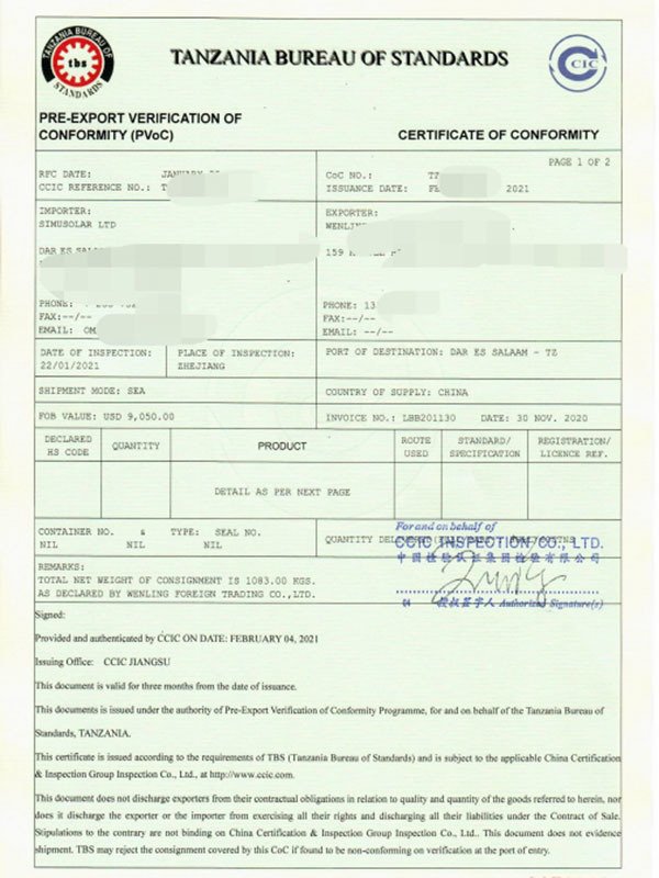
Having standard IEC or TÜV certificates is only the baseline. In real-world global trade, localized customs regulations can easily disrupt your project timeline if your supplier lacks export expertise. For instance, when exporting PV components and energy storage systems to East African markets like Tanzania, standard factory test reports are insufficient. Your cables and entire electrical systems must pass rigorous pre-export verification to secure a COC (Certificate of Conformity) under the local PVoC program. A minor discrepancy in the cable's cross-section data or an unverified insulation material can lead to containers being stalled at the destination port.
At Shanghai Sunvis New Energy Co., Ltd., as an one stop solar solutions supplier, we don't just calculate wire gauges; we secure your supply chain. Our engineering and export teams ensure that every cable specification—from voltage ratings to UV-resistant jacket materials—strictly aligns with both international electrical standards (IEC 62930, NB/T 42060) and the specific customs compliance requirements of your destination country, guaranteeing zero clearance delays.
Secure Your Next Solar Project with Certified Components
Don't let subpar wiring compromise your system's ROI. Partner with an experienced manufacturer providing turnkey solar lighting, BESS storage solutions, and high-performance cabling tailored to your exact project parameters.
*Contact our technical engineering team for project-specific voltage drop calculations and bulk wholesale pricing.





 English
  Español
  Français
  Русский